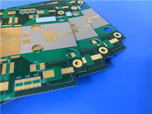
Taconic TRF-45 2-Layer 0.9mm Immersion Gold PCB – Satellite & GPS Antenna
1.Introduction to TRF-45 PCB
The TRF-45 laminated materials represent a new generation of low-loss, thermally-stable laminated material from Taconic Advanced Dielectric Division. TRF-45 is woven-glass reinforced for enhanced dimensional-stability and coupled with Taconic's expertise in ceramic technology. It exhibits low and consistent Z-axis expansion across a wide range of temperature including and up to soldering conditions.
TRF-45 can be sheared, drilled and plated using standard methods for PTFE woven fibre-glass materials.
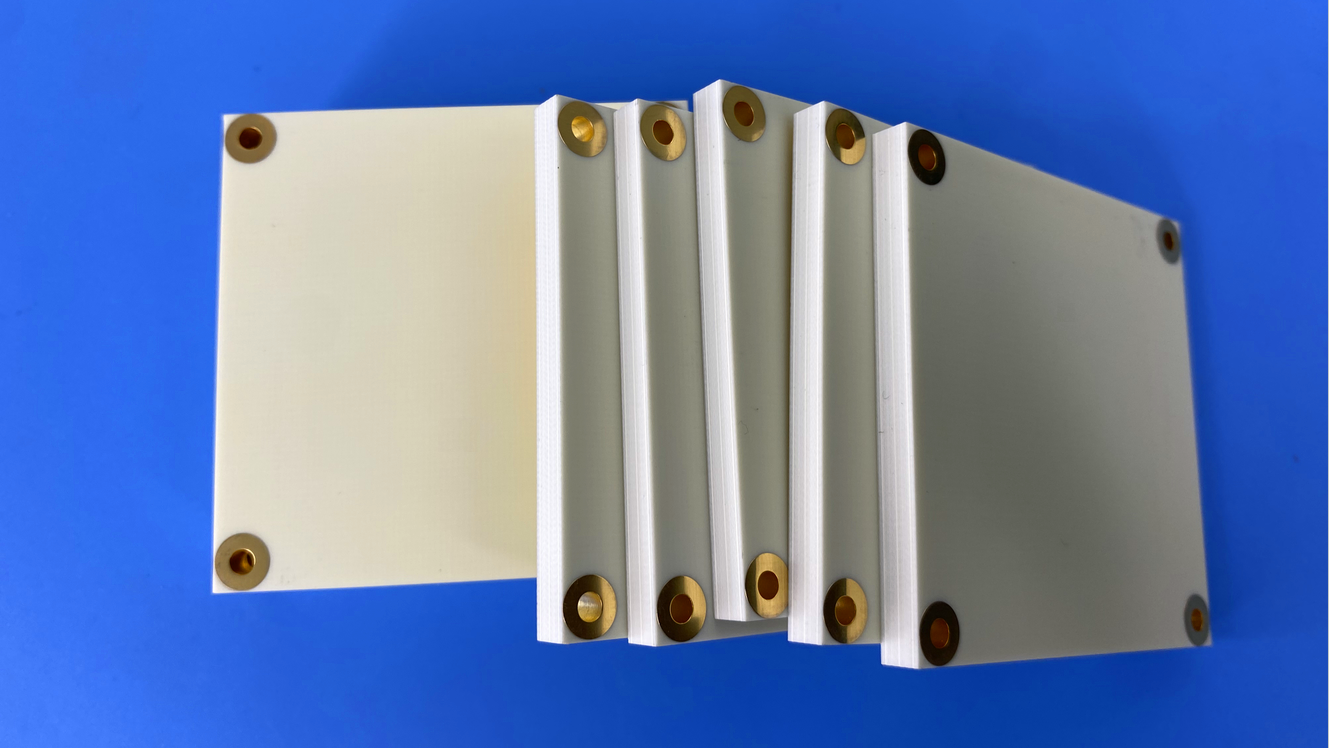
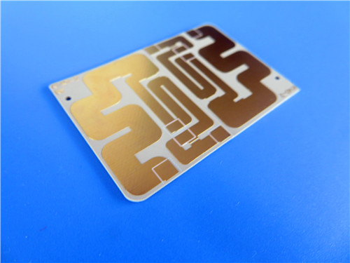
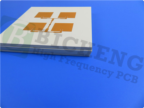
This 2-layer rigid PCB is constructed entirely with TRF-45 as the core material, providing excellent signal integrity, thermal stability, and low-loss performance for demanding RF and antenna applications.
2.Key Features of TRF-45 PCB
Low-loss ceramic-filled PTFE Stable Dielectric constant (Dk) of 4.5 ± 0.15 at 10GHz over temperature and frequency Dissipation factor of 0.0035 at 10GHz Moisture absorption of 0.06% X-axis CTE of 9 ppm/°C, Y-axis CTE of 9 ppm/°C, Z-axis CTE of 40 ppm/°C (50°C to 150°C) Thermal conductivity of 0.43 W/mk Flammability of UL 94-V0
3.Benefits of TRF-45 PCB
Low-loss for excellent high-frequency performance Thermally stable across wide temperature range Low and consistent Z-axis expansion up to soldering conditions Enhanced dimensional stability due to woven-glass reinforcement Can be processed using standard PTFE woven fiberglass methods (shearing, drilling, plating) Stable dielectric constant over temperature and frequency
4.TRF-45 PCB Construction Details
| Item | Specification |
|---|
| Base material | TRF-45 |
| Layer count | Double sided |
| Board dimensions | 105mm x 76mm = 1PCS, +/- 0.15mm |
| Minimum Trace/Space | 4/6 mils |
| Minimum Hole Size | 0.25mm |
| Blind vias | No |
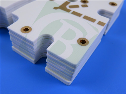
| Finished board thickness | 0.9mm |
| Finished Cu weight | 1oz (1.4 mils) outer layers |
| Via plating thickness | 20 μm |
| Surface finish | Immersion Gold |
| Top Silkscreen | White |
| Bottom Silkscreen | No |
| Top Solder Mask | Green |
| Bottom Solder Mask | No |
| 100% Electrical test | Used prior to shipment |
5.PCB Stackup (2-Layer Rigid Structure)
Copper_layer_1 – 35 μm
TRF-45 Core – 0.813 mm (32 mil)
Copper_layer_2 – 35 μm
6.PCB Statistics
Components: 42
Total Pads: 38
Thru Hole Pads: 25
Top SMT Pads: 13
Bottom SMT Pads: 0
Vias: 15
Nets: 2
7.Primary Application Areas
Satellite radio antennas RFID antennas GPS antennas
8.Quality Assurance
Artwork supplied: Gerber RS-274-X
Accepted standard: IPC-Class-2
Availability: Worldwide
9.TRF-45 Low-Loss Ceramic-Filled PTFE – Product Introduction
The TRF range of laminated materials represent a new generation of low-loss, thermally-stable laminated material from Taconic Advanced Dielectric Division.
TRF is woven-glass reinforced for enhanced dimensional-stability and coupled with Taconic's expertise in ceramic technology. TRF exhibits low and consistent Z-axis expansion across a wide range of temperature including and up to soldering conditions.
TRF-45 can be sheared, drilled and plated using standard methods for PTFE woven fibre-glass materials.
10.Features and Benefits
Key Features
Low-loss ceramic-filled PTFE Stable Dielectric constant (Dk) of 4.5 ± 0.15 at 10GHz over temperature and frequency Dissipation factor of 0.0035 at 10GHz Moisture absorption of 0.06% X-axis CTE of 9 ppm/°C, Y-axis CTE of 9 ppm/°C, Z-axis CTE of 40 ppm/°C (50°C to 150°C) Thermal conductivity of 0.43 W/mk Flammability of UL 94-V0
Benefits
Low-loss for excellent high-frequency performance Thermally stable across wide temperature range Low and consistent Z-axis expansion up to soldering conditions Enhanced dimensional stability due to woven-glass reinforcement Can be processed using standard PTFE woven fiberglass methods
11.TRF-45 Data Sheet
| Property | Test Method | Units | TRF-45 Typical Value |
|---|
| Dielectric Constant | IPC-TM-650 2.5.5.6 | – | 4.5 ± 0.15 |
| Dissipation Factor | IPC-TM-650 2.5.5.1(m) | – | 0.0035 at 10GHz |
| Moisture Absorption | IPC-TM-650 2.6.2.1 | % | 0.06 |
| Surface Resistivity | IPC-TM-650 2.5.17.1 | Mohm | 3.0 × 10⁷ |
| Volume Resistivity | IPC-TM-650 2.5.17.1 | Mohm·cm | 8.0 × 10⁷ |
| Flexural Strength (Lengthwise) | IPC-TM-650 2.4.4 | lbs/in (N/mm²) | 17,000 (177) |
| Flexural Strength (Crosswise) | IPC-TM-650 2.4.4 | lbs/in (N/mm²) | 15,000 (103) |
| Peel Strength | IPC-TM-650 2.4.8 | lbs/in (N/mm) | 8 (1.4) |
| Thermal Conductivity | ASTM F433 | W/m·K | 0.43 |
| CTE (X axis, 50-150°C) | ASTM D3386 (TMA) | ppm/°C | 9 |
| CTE (Y axis, 50-150°C) | ASTM D3386 (TMA) | ppm/°C | 9 |
| CTE (Z axis, 50-150°C) | ASTM D3386 (TMA) | ppm/°C | 40 |
| Flammability | UL-94 | Class | V-0 |
12.Some Typical Applications
Satellite radio antennas RFID antennas GPS antennas
13.Standard Thicknesses, Panel Sizes & Claddings
Standard Thicknesses
| Inches | mm |
|---|
| 0.0080 | 0.20 |
| 0.0160 | 0.41 |
| 0.0240 | 0.61 |
| 0.0320 | 0.81 |
| 0.0400 | 1.02 |
| 0.0640 | 1.63* |
| 0.1200 | 3.05* |
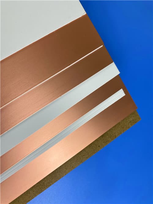
Copper Cladding Options
| Designation | Weight | Copper Thickness | RMS Treated Side | Description |
|---|
| CLH | 1/2 oz/ft² | ~0.0007" (~18μm) | 13μm / 0.3μm | Reverse treated / Electrodeposited |
| CL1 | 1 oz/ft² | ~0.0014" (~35μm) | 13μm / 0.3μm | Reverse treated / Electrodeposited |
| CVH (CH) | 1/2 oz/ft² | ~0.0007" (~18μm) | 27μm / 0.7μm | Very low profile / Electrodeposited |
| CV1 (C1) | 1 oz/ft² | ~0.0014" (~35μm) | 25μm / 0.6μm | Very low profile / Electrodeposited |
| C2 | 2 oz/ft² | ~0.0028" (~70μm) | 77μm / 2.0μm | Electrodeposited |
|